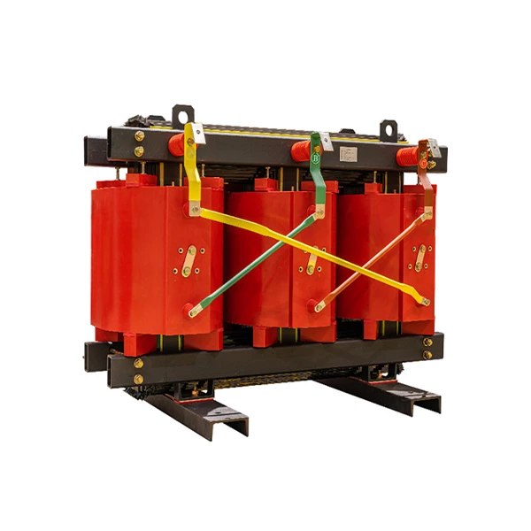
Epoxy Resin All Copper Dry Type Transformer
- Application:
- Power
- Transport Package:
- Plywood Box
- Origin:
- Zhejiang, China
Normal operation condition
Altitude < 1000 m Indoor
Max. Ambinet temperature +40ºC
Max. Daily average temperature + 30ºC
Max. annual average temperature +20ºC
Min. temperature -5ºC
Supply transformers operate under special conditions according to customer requirements.
Features
1. The core is made of cold rolled grained high-oriented silicon steel sheets that thickness ≤0.3mm with 45 degree mitred joints. The surface is coated with special resin for moisture and rust proof.
2. Normally the LV winding materials is copper foil cylinder type excepet for small capacity transformers which LV winding materials is copper wire; The HV winding structure is multi-layer cylinder type that has good ampere-turn balance, low leakage flux, high mechanical strength and strong short-circuit withstand capability.
3. By installing the low noise fans that controled by the temperature control device,the operation capacity of the transformer can be increased by 40%.
4. The temperature device which sensers buried in LV winding can control the fans or send alarm & trip signals to protect the transformer.
5. The transformer can be installed in a enclosure which protetion class is IP20 or IP23, the enclosure can prevent small animals coming inside the transformer to avoid short circuit, and also safeguard the personal safety.
6. Sc(b)9 No-load losses Equal To Standard Value In GB/T10228-2008
No-load losses Equal To Tagged Value In GB/T10228-2008
Sc(b)10 No-load losses Decrease By 10% Compared with Standard Value In GB/T10228-2008
No-load losses Decrease By 5% Compared with Tagged Value In GB/T10228-2008
Technical Data
35KV main 50kVA~2500KVA NLTC distribution transformer
| Nominal capacity(KVA) |
Voltage unitcombination | Low voltage(KV) | Vector Group | No-load loss(W) | Loasloss (W) | No-load current(%) | Short-circuit impedance(%) | ||
| High voltage(KV) |
High voltage tap range |
F class (120ºC) |
H class (120ºC) |
||||||
| 50 | 35 36 37 38.5 |
±2×2.5% or ± 5% |
0.4 |
Yyn0 Dyn11 |
450 | 1420 | 1520 | 2.3 | 6.0 |
| 100 | 630 | 2090 | 2230 | 2.0 | |||||
| 160 | 790 | 2810 | 3000 | 1.5 | |||||
| 200 | 880 | 3320 | 3550 | 1.5 | |||||
| 250 | 990 | 3800 | 4060 | 1.3 | |||||
| 315 | 1170 | 4510 | 4820 | 1.3 | |||||
| 400 | 1370 | 5410 | 5790 | 1.1 | |||||
| 500 | 1620 | 6650 | 7110 | 1.1 | |||||
| 630 | 1860 | 7690 | 8230 | 1.0 | |||||
| 800 | 2160 | 9120 | 9760 | 1.0 | |||||
| 1000 | 2430 | 10400 | 11100 | 0.75 | |||||
| 1250 | 2830 | 12700 | 13600 | 0.75 | |||||
| 1600 | 3240 | 15400 | 16500 | 0.75 | |||||
| 2000 | 3820 | 18200 | 19500 | 0.75 | |||||
| 2500 | 4450 | 21800 | 2330 | 0.75 | |||||
35KV main 800kVA~25000KVA NLTC Power transformer
| Nominal capacity(KVA) |
Voltage unitcombination | Low voltage(KV) | Vector Group | No-load loss(W) | Loasloss (W) | No-load current(%) | Short-circuit impedance(%) | ||
| High voltage(KV) |
High voltage tap range |
F class (120ºC) |
H class (120ºC) |
||||||
| 800 | 35 36 37 38.5 |
±2×2.5% or ± 5% |
3.15 6 6.3 10 10.5 11 |
Yyn0 Yd11 Dyn11 |
2250 | 9400 | 10000 | 0.95 | 6.0 |
| 1000 | 2670 | 10900 | 11600 | 0.95 | |||||
| 1250 | 3130 | 12900 | 13800 | 0.85 | |||||
| 1600 | 3690 | 15400 | 16500 | 0.85 | |||||
| 2000 | 4230 | 18200 | 19500 | 0.75 | 7.0 | ||||
| 2500 | 4860 | 21800 | 23300 | 0.75 | |||||
| 3150 | 6030 | 24500 | 26200 | 0.70 | 8.0 | ||||
| 4000 | 7020 | 29400 | 31500 | 0.70 | |||||
| 5000 | 8370 | 34900 | 37400 | 0.60 | |||||
| 6300 | 9900 | 40800 | 43700 | 0.60 | |||||
| 8000 | Ynd11 Yd11 Dyn11 |
11300 | 46000 | 49300 | 0.50 | 9.0 | |||
| 10000 | 12900 | 55500 | 59400 | 0.50 | |||||
| 12500 | 6 6.3 10 10.5 |
15700 | 64600 | 69100 | 0.40 | ||||
| 16000 | 19300 | 76000 | 81300 | 0.40 | |||||
| 20000 | 22900 | 85500 | 91500 | 0.35 | 10.0 | ||||
| 25000 | 27100 | 101000 | 108000 | 0.35 | |||||
35KV main 2000kVA~25000KVA OLTC Power transformer
| Nominal capacity(KVA) |
Voltage unitcombination | Low voltage(KV) | Vector Group | No-load loss(W) | Loasloss (W) | No-load current(%) | Short-circuit impedance(%) | ||
| High voltage(KV) |
High voltage tap range |
F class (120ºC) |
H class (120ºC) |
||||||
| 2000 | 35 36 37 38.5 |
±4×2.5% |
3.15 6 6.3 10 10.5 11 |
Yd11 Dyn11 |
4500 | 19000 | 20300 | 0.75 | 7.0 |
| 2500 | 5220 | 22600 | 24200 | 0.75 | |||||
| 3150 | 6300 | 25400 | 27200 | 0.70 | 8.0 | ||||
| 4000 | 7380 | 30400 | 32600 | 0.70 | |||||
| 5000 | 8730 | 36100 | 38600 | 0.60 | |||||
| 6300 | 10300 | 41800 | 44700 | 0.60 | |||||
| 8000 | 11800 | 47500 | 50800 | 0.50 | 9.0 | ||||
| 10000 | 13500 | 57100 | 61200 | 0.50 | |||||
| 12500 | 16400 | 66500 | 71100 | 0.40 | |||||
| 16000 | 20200 | 78200 | 83700 | 0.40 | |||||
| 20000 | 23800 | 88000 | 94200 | 0.35 | 10.0 | ||||
| 25000 | 28100 | 104000 | 111000 | 0.35 | |||||
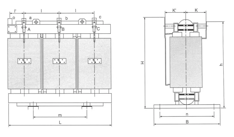
Note: The physical dimension in the manual is only provided for design reference, and the fimal dimension shall be based on the actual outline drawing.


